Topics in Photographic Preservation 2007, Volume 12, Article 18 (pp. 114-125)
Presented at the 2007 Joint PMG/ICOM-CC WGPM Meeting, Rochester, New York
Photo conservators are facing increasing numbers of damaged face-mounted photographs. Acrylic sheet is mainly used as the facing material and is susceptible to scuffing, scratching, and gouging. This study is a survey of commercially available uncoated and hard-coated acrylics and polycarbonates that may provide improved scratch and abrasion resistance. Some of the hard-coated materials are currently used in products such as locomotive and airplane windows as well as automotive headlamp, where a silicone hard-coat is used as an abrasion resistant coating.
Acrylic, hard-coated acrylic, polycarbonate, and hard-coated polycarbonate were compared. Scratch resistance was evaluated using two methods: Crockmeter and single point stylus. Each produced a different type of damage ranging from light abrasion to deep gouging. When available, damage from works of art was examined and compared to the damage produced by these methods. The damage was quantified by optical profilometry and transmission spectroscopy. Methods for repairing scratched hard-coated surfaces are being developed.
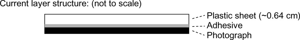
Face-mounting a photograph involves adhering the front side of a photograph to a transparent plastic sheet (Figure 1). The conservation literature includes discussions of the lamination.1,2 as well as the long term stability3 of a typical face-mounted photograph. The adhesive is typically a transparent silicone but can also be a polyester or poly(vinyl chloride) film coated on both sides with a pressure sensitive acrylic.1 Acrylic is the most common plastic sheet used, and the identification4, degradation,4,5,6 treatment,4,7,8 and effect of solvents9 on acrylic have been discussed previously. Some artists choose to add layers of support or protection to the verso of the photograph (not shown in Figure 1).
Figure 1. Basic face-mounted layer structure.
The face-mounting of photographs offers several advantages to the artist and has become a common method for displaying large works.1,10 Significant advantages are the wet or saturated look that is produced and the lack of a need for a frame, which leads to reduced cost and weight. While acrylic sheet can be hard, transparent, UV-protective, and produced in various sizes, its surface is susceptible to scratches during cleaning, polishing, and moving.2,11 Since the acrylic is irreversibly bound to the photograph, it is not easily replaced, and scratches are generally either left in place or removed via polishing.4,7,8,12
The following study compares the resistance to both deep scratches and light abrasions of commercially available acrylics, polycarbonates, and hard-coated acrylics and polycarbonates. The discussion and results focus on acrylics and hard-coated acrylics due to the ease of scratching and poor optical performance generally found for polycarbonates.
All materials used in the study were commercially available. A list of the materials and their physical properties are found in Table 1. Both extruded and cast materials7,14 ranging in thickness from ~2.8 mm (slightly less than 1/8 inch) to 5.4 mm (slightly less than 1/4 inch) were used. Hard-coated samples are denoted with either AR or AR-1, which stands for abrasion resistant and abrasion resistant on one side, respectively. The materials were kindly provided as samples from the Cyro, Plaskolite, Polycast, and General Electric and were cut to 4″ × 4″ squares. The protective liners were removed, and the surfaces were prepared by rinsing with isopropanol followed by drying with compressed air.
Table 1. Physical properties of acrylic and hard-coated acrylics used in this study.
| Manufacturer | Manufacturer process | Onset of absorption (nm) | Thickness* (mm) | |
| Acrylite FF3 (Cyro) | Cyro | extruded | 389 | 2.86 |
| Optix (Plaskolite) | Plaskolite | extruded | 393 | 2.92 |
| Acrylic UF96 (Polycast) | Polycast | cell cast | 422 | 4.94 |
| Acrylite OP2 (Cyro) | Cyro | cell cast | 422 | 5.39 |
| Acrylite OP3 (Cyro) | Cyro | extruded | 421 | 2.82 |
| Optix AR1, Acrylic-side (Plaskolite) | Plaskolite | extruded | 393 | 5.52 |
| Optix AR1 Acrylic, HC-side (Plaskolite) | Plaskolite | extruded | 393 | 5.52 |
| Acrylite OP3 AR - HC side (Cyro) | Cyro | extruded | 420 | 2.89 |
* Thickness measured with vernier calipers using the average of 3 measurements
A Varian Cary 50 Bio UV-Visible Spectrophotometer was used to record the onset of ultraviolet light absorption for both coated and uncoated samples in this study. The general settings of the instrument were the following: 1) scan range = 830–260nm, 2) Beam mode = dual, 3) Averaging time = 0.0125 seconds, and 4) data interval = 1nm. The onset of absorption was recorded as the wavelength at which the absorption was closest to 0.1 absorbance units. All materials produced absorption of less than 0.1 absorbance units for wavelengths greater than the onset of absorption wavelength. For example, Acrylite FF3 produced very little to no absorbance of wavelengths greater than 389nm (up to the measurement limit of 830nm). UV-Visible spectra were taken of each sample, and the onset of absorption is noted in Table 1. The materials with onset of absorption values around 420 nm contained UV-absorbing additives mixed into the bulk material. Those with values at 390 nm lacked UV-absorbing additives.
Light abrasions were created using an American Association of Textile Chemists and Colorists (A.A.T.C.C.) Crockmeter model CM 1. The Crockmeter was outfitted with a 0.5 inch (1.27 cm) diameter tip.17 The arm applied 9 Newtons of vertical force across the 1.27 cm2 tip area. The tip was covered with either 2 or 15 micron silicon carbide (SiC) particle impregnated cloth available from 3M.18 The cloth was fixed to the Crockmeter in a wrinkle free manner by placing the cloth on a swatch of felt. The felt side was put over the tip, and a hose clamp was opened to slightly greater than 0.5 inch diameter and slid over the cloth (similar to the process of stretching fabric in a needlepoint or embroidery hoop). A single piece of cloth was used for each sample. The process involved holding the sample in place under the scratch head by hand. No solvents or lubricants were used under the scratch head. The sample was scratched for 1 cycle, and the haze was measured. The sample was then remounted, and the same area was scratched an additional 24 cycles (for a total of 25 cycles). Haze was re-measured. This was repeated with an additional 75 cycles for some samples.
The term ‘cycles’ refers to one turn of the crank during which the tip crosses the sample twice in a single down and back motion.
Haze was measured using a BYK-Gardner Haze-Gard plus haze meter. The light port leading to the integrating sphere was covered with a piece of black rubber with a 0.5″ hole cut into the center to match the width of the scratches being produced by the 0.5″ Crockmeter head. Samples were placed against the integrating sphere side of the machine with the scratched surface facing the light source for measurement.
The error in this measurement was determined by using sets of samples of XL10 polycarbonate and OP2 acrylic prepared on the Crockmeter. Each sample was abraded using 2 and 15 micron polishing papers at 1 and 25 cycles. This was repeated three times and measured at four different places along the scratch. The error for haze measurement was determined to be 12%.
Single Point Stylus Scratcher - An apparatus to apply scratches reproducible in size to ± 0.1 μm was built at General Electric's Global Research Center. A first generation stylus scratching machine was built and previously described.13 Modifications to the original design are described here. Scratches were made using a diamond-tipped indenter that moved along a sample surface under a constant or increasing normal load. The indenter was moved in the vertical direction using a Parker Daedal Cross Roller Bearing stage. X-Y motion was provided by two other Cross Roller Bearing stages. A Compumotor 6K4 Controller guided the three Roller Bearing stages. All three stages had a resolution of 0.000635 mm. The X & Y stages had a total travel of 150 mm, while the Z (vertical) axis had a travel of ˜ 27 mm. The minimum normal force that could be applied was 50 mN. The indenter was mounted on a JR3 3-axis Force transducer, which provided feedback to enable the 6K4 Controller to actively produce small vertical motions that compensated for sample tilt or curvature to maintain constant normal force. Typical loads were in the range of 0.5N to 30 N, and it was capable of applying up to 60 Newtons of force. The applied force during a single scratch could either be constant or variable, i.e. gradually increased or decreased at a constant rate.
Two types of scratches were generated using the single point stylus scratcher. The first is referred to as the ‘break through force”. Determining the break through force involved pressing a 400 micron tip with a 90° cone angle with a force of 0.1 Newtons on the surface. When 0.1 Newtons of force was attained, the sample was translated under the stylus over a distance of 30 mm while continuously and gradually increasing the force to 16 Newtons. Using both the naked eye and a Keyence model VHX-500K optical microscope the point at which a scratch began to form was recorded. Because the rate of force increase was constant, and the distance traveled known, the force needed to break through the surface could be calculated and is presented in figure 3. The second experiment was to attempt 4 constant force scratches at 1, 6, 11, and 16 Newtons. If the applied force was greater than the break through force, a scratch was visible. The geometry of each scratch was analyzed with an optical profilometer. Trough depth, trough width, and displaced material height were measured (Figure 2). In all cases, the scratch speed was set to 0.1 mm/s, and the stylus was set to regulate the force based on the topography of the surface.
Profilometry Measurement: An ADE Phase Shift MicroXAM (Michelson configured) optical profilometer was used to measure the 3-dimensional profile of deep scratches. Magnification was set at 6.2x using 10x objective combined with 0.62x intermediate magnifier. figure 2 shows a schematic of a typical cross-section and the boundaries used for recording the trough width, depth, and displaced material height.
The percent error of measurements taken of 24 scratches (16N of force in both OP3 and the acrylic side of Optix AR1 (12 scratches each)) was determined for the trough depth, trough width and displaced material height (4.9%, 1.4%, and 8.1%, respectively).
Figure 2. Schematic of trough cross-section with trough width, depth and displaced material height measurements noted.
Six acrylic and two hard-coated acrylics as well as five polycarbonates and three hard-coated polycarbonates were compared by submitting them to deep gouging and light abrasion testing. A general discussion of the results for polycarbonates is in the following paragraph, but the details are not disclosed in this report. All other results will focus on acrylics.
The main advantage of polycarbonates is that they are extremely shatter resistant. Commercially available sheet polycarbonates (GE's Lexan 9034 and XL10) greatly underperformed relative to acrylics in both deep gouge and light abrasion testing, and the same was true for hard-coated polycarbonate (GE's MR101) relative to hard-coated acrylics. A new polycarbonate resin from General Electric's Plastics division (GEP) named DMX 2415 was available only in pellet form and not in sheet form. Small plaques of DMX 2415 were hand cast at GEP as 4 inch square, 3.2 mm thick samples. Hand cast hard-coated sample were also supplied as 4 inch diameter, 3.1 inch thick discs. DMX 2415 has fairly poor optical qualities (it appears slightly grey), but is much harder than standard polycarbonate (Lexan 9034). DMX 2415 is reported to have a five-times higher pencil hardness than standard polycarbonate by GEP.15 The uncoated and hard-coated DMX 2415 were less easily scratched than Lexan 9034 and MR101, respectively. Acrylic and hard-coated acrylic samples, however, were even less easily scratched than the uncoated DMX 2415 and hard-coated DMX 2415 samples, respectively. While DMX 2415 appears to be a significant advance in the hardness of polycarbonates, which dramatically improves its scratch resistance relative to standard polycarbonate, the poor optical qualities will likely preclude use of DMX 2415 in museum glazing applications. As DMX 2415 is a very new product, improvements may be underway to decrease slight grey coloring. If the color is improved, this material may be considered for museum applications.
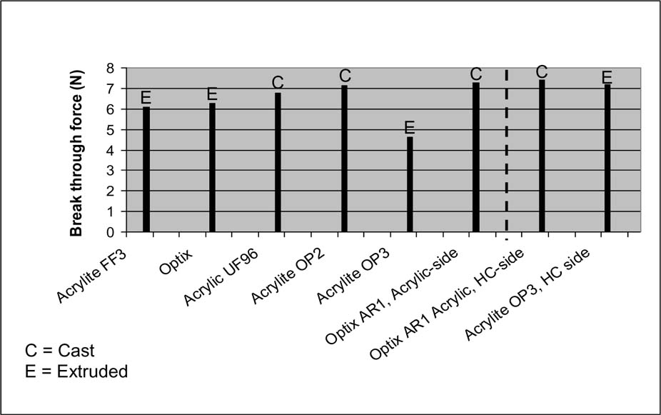
The remaining results focus on acrylic and hard-coated acrylic materials. The break through force data from Figure 3 shows a comparison of acrylic and hard-coated acrylic materials displaying extruded (labeled E) or cast (labeled C) production methods. The data shows an insignificant change in break through force between hard-coated and uncoated acrylics. Cast and extruded samples also showed negligible differences with regard to the minimum force required to initiate deep scratches. The best comparison of an acrylic versus a hard-coated acrylic is between the one-side coated Optix AR1 acrylic from Plaskolite. By testing the hard-coated and uncoated sides of this sample, the effect of the hard-coat was shown to be negligible (7.4 N and 7.3 N, respectively). Differentiation between cast and extruded material was possible by comparing the uncoated materials. In only one case (Optix AR-1, Acrylic side) was the break through force approximately the same as the best performing cast material (Acrylite OP2). In all other uncoated acrylics, the extruded materials required less force to initiate scratching. Only one outlier exhibited a very low break through force - Acrylite OP3 by Cyro.
Figure 3. Break through force using a 400 micron diameter 90 degree diamond stylus.
The optical profilometry data in Table 2 shows differences between the very best and poorest performers with regard to deep gouging at 16 Newtons of applied force. The best two of each category are highlighted in grey. In the case of trough depth, width, and displaced material height, the acrylic sheet Acrylite FF3 outperformed (or was virtually identical to) all other materials. Optix and Acrylite OP3 share the position for poorest performer depending on the category. This test does not conclusively differentiate cast versus extruded materials.
Light abrasions were created using a Crockmeter, which is a relatively simple, inexpensive ($400–1000), and commercially available piece of equipment. Haze measurements through the scratched region before and after abrading were used to evaluate the damage to the sample from two polishing cloths embedded with 2 or 15 micron SiC particles. The results for representative acrylics and hard-coated acrylics with 2 or 15 μm polishing paper are shown in Figures 4 and 5, respectively. Only two of the acrylic samples are reported in these figures, however, data were collected for all acrylics discussed in this report. The results shown for Acrylic UF96 and Acrylite OP2 are representative of all uncoated acrylics in this study.
Scratches produced with 2 μm polishing paper were visually apparent even after one cycle for the acrylic samples (Figure 4). This was not the case for the hard-coated materials, where no visible marks were apparent and change in haze was not detectable. Because the same piece of polishing paper was used on a particular sample, some samples showed a polishing effect. As the particles of acrylic being removed from the surface were embedded into the cloth and rubbed on the surface, the surface became smoother and exhibited decreased haze values (example: Figure 4, Acrylite OP2).
Figure 4. Percent haze of light abrasions in acrylic and hard-coated acrylic created with polishing paper embedded with 2 μm SiC particles mounted in Crockmeter.
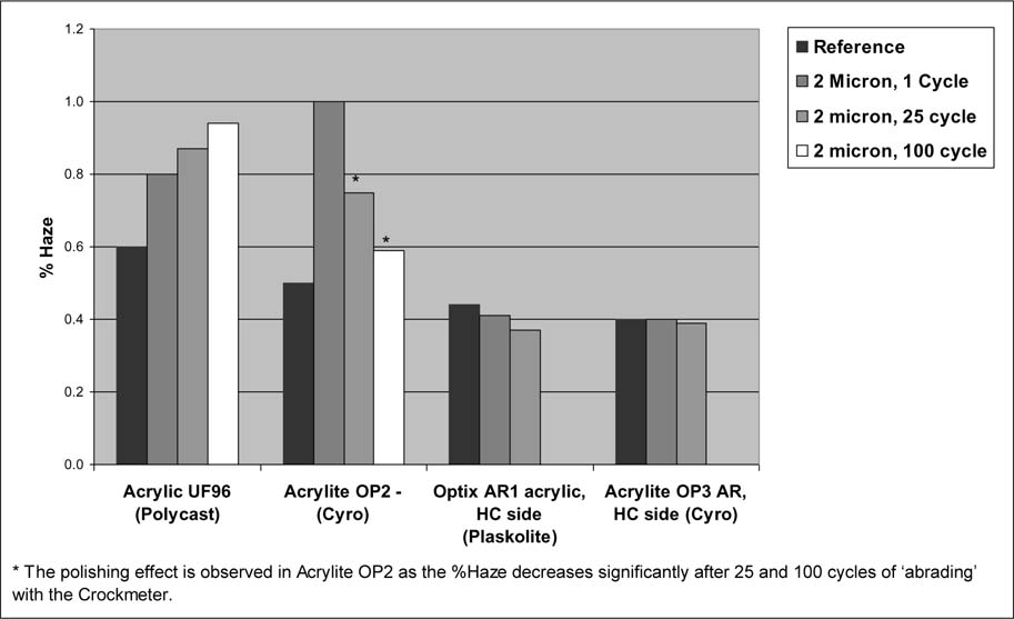
Table 2. Stylus scratch data at constant 16 Newton load.
| Sample | Manufacturing Process | Width (microns) | Depth (microns) | Displaced material height (microns) |
| Acrylite FF3 (Cyro) | Extruded | 187.1 | 1.1 | 0.4 |
| Optix (Plaskolite) | Extruded | 278.0 | 1.9 | 2.3 |
| Acrylic UF96 (Polycast) | Cast | 277.9 | 1.4 | 1.2 |
| Acrylite OP2 (Cyro) | Cast | 268.0 | 1.4 | 1.1 |
| Acrylite OP3 (Cyro) | Extruded | 261.4 | 2.2 | 1.5 |
| Optix AR-1, Acrylic-side (Plaskolite) | Extruded | 268.0 | 1.1 | 0.7 |
| Optix AR-1 Acrylic, HC-side (Plaskolite) | Extruded | 224.1 | 1.4 | 0.9 |
| Acrylite OP3 AR, HC side (Cyro) | Extruded | 276.8 | 1.2 | 1.0 |
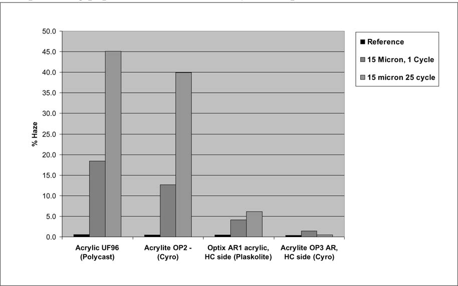
Using 15μm polishing paper (Figure 5), abrasions were visually apparent even after one cycle for both the uncoated and hard-coated acrylic samples. The difference between uncoated and hardcoated was most evident in this test, where uncoated acrylics registered haze values of 13.1% and 19% after 1 abrasion cycle, and the hard-coated samples showed minimal damage of 1.8% and 4.6%. This effect is even more exaggerated after 25 cycles, where the acrylic samples became much more hazy (40.3% and 45.7%), and the hard-coated materials maintained relatively low haze values (0.9% and 6.6%).
Figure 5. Percent haze of light abrasions in acrylic and hard-coated acrylic created with created with polishing paper embedded with 15 μm SiC particles mounted in Crockmeter.
The y-axis scale difference between the plots in Figures 3 and 4 is noteworthy. The difference between the haze of Acrylic UF96 before scratching (0.5%) and after 1 cycle with the 2μm polishing paper (0.8%) is only 0.3%. This difference was visibly apparent with the naked eye, however, it was possible to light the hazy area from the 1 cycle scratch such that it was difficult to observe. Abrasions that lead to haze values greater than 1% were visually readily apparent and became more difficult to mask with lighting techniques.
The two methods of scratching the surface of acrylic or hard-coated acrylic in this study (Crockmeter and single point stylus) were chosen to mimic light abrasions and deep gouges, respectively. Light abrasions refer to scratches often produced during routine cleaning of a face-mounted photograph with a dry or wet cloth. These often appear as large circular patterns as dust or small particles from a cleaning cloth abrade the surface. Deep gouges can be caused by hard, sharp objects being dragged across the surface.
The single point stylus data shows little to no difference between cast and extruded. Both cast acrylics in this study were cell cast materials, and neither were annealed.16 Non-annealed cell cast acrylics suffer from length and width dimensional instability (shrinkage) due to internal stresses generated during the initial curing process. The same is true for extruded materials that are known to shrink lengthwise and expand widthwise due to stresses incurred in the extrusion process. Other significant differences exist between cast and extruded acrylic sheet include polymer chain length (shorter or lower molecular weight polymer is used for extruded than cast), linear versus three-dimensional interlocked polymer network (cast has a cross-linked/chemically locked (3-D) structure, and extruded sheet has entangled, linear chains that are not chemically linked).7 None of these factors seem to affect the resistance to scratching.
The single point stylus data also shows no difference between a particular acrylic and the hard-coated version of that acrylic. Two examples are shown; Optix AR-1, Acrylic side versus Optix AR-1 Acrylic, Hard-coat side and Acrylite OP3, HC side versus Acrylite OP3. The Optix samples compare well to each other for scratch width, depth, and displaced material height. The OP3 samples compare well for scratch width and displaced material height, though the depth of scratch for the uncoated OP3 (2.2 μm) is approximately twice as deep as the hard-coated OP3 (1.2 μm).
A similar comparison is possible between Optix and Optix AR-1, Acryl side. These show very different depth and displaced material heights. According to the Plaskolite representatives, Optix acrylic sheet is used as the substrate for the Optix AR-1 product. Because of this, the non-coated side of the AR-1 product was expected to have similar physical properties as the Optix sheet. The Optix material, however, resulted in a deeper and wider trough as well as more displaced material in the single stylus scratch test. The reasons for this difference are not clear. There are processing differences between the two sheets, and it is possible that the differences in scratch results may be attributed to the processing required for preparing and curing the hard-coat. Another possibility is that the sheets were produced from different batches of Optix sheet where differences in physical properties existed.
While the data doesn't significantly distinguish acrylics and hard-coated acrylics, the scratches in acrylic were smooth and difficult to see at all viewing angles, and the scratches in the hard-coated acrylics were rough and appeared white at most viewing angles. Smooth scratches are indicative of plastic deformation, where the acrylic polymer moves and repositions as it is damaged such that a new shape (trough) is formed, but the surface is not cracked or ruptured. A rough or white scratch is indicative of brittle deformation, where the surface of the hard-coat fractures and cracks under the stress of the stylus. Acrylics are known for brittle deformation, however, a force of 16 Newtons with the tip used in these experiments was not great enough to incur fracturing. It was clear from these experiments that the force required to observe fracturing was greater for acrylics than for hard-coated acrylics.
Distinguishing between uncoated and coated acrylic was also possible by using the Crockmeter test. This was not a surprising result as several manufactures of hard-coated acrylics demonstrate their product by rubbing steel wool on the surface without noticeably scratching it. For this study, both 2μm and 15μm polishing papers created a greater amount of haze and scratches on the uncoated samples than the hard-coated samples.
The results from this study show that both hard-coated and uncoated acrylics are susceptible to deep gouging, but that hard-coated acrylics are much less likely to endure damage from light abrasion than uncoated acrylics. And while some artists or museums may prefer the ability to clean the recto of their face-mounted photographs, more tests are needed to determine the repairability of hard-coated materials before fully recommending the use of hard-coated materials to museums and collectors.
To date, no reversible method of repair is available for either uncoated or hard-coated acrylic. The only method of repair for uncoated acrylic and either type of damage (light abrasion and deep gouging) is polishing. The surface of acrylic is very flat when produced properly. Hand or machine polishing to a similar flatness is difficult and easily detected; minor deviations in surface topography are easily observed as light reflects non-uniformly from the surface. If a deep gouge must be polished, a much larger area than the initial damage is typically polished to create a gradual transition from the unscratched surface height to the bottom of the scratch. Deeper scratches usually require larger areas to be polished to blend the damaged and undamaged areas. This type of repair leaves a bowled or dished surface at the repaired area because more material is removed at the scratch and less is removed from the surrounding area.
The ability to repair deep scratches using standard polishing techniques is an advantage over hard-coated acrylics. Even though the results are not exactly what the artist originally intended due to the dishing effect, once damaged, an option exists for changing a deep gouge into a shallow bowl with similar reflective optical properties as the original surface. This may not be an option with hard-coated acrylics. Because hard-coats are only 5–20 microns thick, scratches that do not penetrate the coating may be polished, but polishing only the hard-coated material can be difficult or nearly impossible without breaking through the hard-coat layer. Those scratches that penetrate the hard-coating may not be easily polished either. George Laurence of Museum Acrylics reports that small areas or spots of acrylic can become exposed during polishing, which leads to a non-uniform appearance.12
A thorough scientific study of the repair methods and repairability of both uncoated and hard-coated acrylic sheet is needed. A preliminary survey of potential acrylic and epoxy fill materials is underway at the Metropolitan Museum of Art and the Conservation Center of the Institute of Fine Arts, New York University. The materials being tested will likely translate well to hard-coated acrylics due to their similar refractive indices and similar mode of failure to acrylics during scratching. It is possible that hard-coated acrylics may also be repaired using the hard-coating liquid precursor to fill a deep gouge followed by light polishing. Thorough filling and polishing studies on hard-coated acrylics are necessary before conclusively recommending for or against their use in face-mounting of photographs.
1 Pénichon, S. Jürgens, M. 2001. Two Finishing Techniques for Contemporary Photographs. Topics in Photograph Preservation 9: 85–96.
2 Pénichon, S. Jürgens, M. 2005. Plastic Lamination and Face Mounting of Contemporary Photographs. In Coatings on Photographs: Materials, Techniques, and Conservation, ed. C. McCabe. Washington, D.C.: American Institute for Conservation. 219–233.
3 Pénichon, S. Jürgens, M. Murray, A. 2002. Light and Dark Stability of Laminated and Face-mounted Photographs: A Preliminary Investigation. In Works of Art on Paper Books, Documents and Photographs: Techniques and Conservation, ed. V. Daniels et al. London: The International Institute for Conservation. 154–159.
4 Blank, S. 1990. An Introduction to Plastics and Rubbers in Collections. Studies in Conservation. 35: 53–63.
5 Willcocks, S. 2002. Transparent Tubes by William Turnbull: the degradation of a polymethyl methacrylate sculpture. 13th Triennial Meeting in Rio de Janeiro, ICOM Committee for Conservation, Preprints Volume II. 935–939.
6 von Oosten, T. B. 2002. Crystals and Crazes: Degradation in Plastics Due to Microclimates. In Plastics in Art: History, Technology, Preservation, ed. T. B. von Oosten et al. Munchen: Restaurierung und Konservierung von Kunst- und Kulturgut. 80–89.
7 Sale, D. 1993. An Evaluation of Eleven Adhesives for Repairing Poly(methyl methacrylate) Objects and Sculpture. In Saving the Twentieth Century: The Conservation of Modern Materials, ed. D. W. Grattan. Ottawa: Canadian Conservation Institute. 325–339.
8 Lorne, A. 1999. The poly(methyl methacrylate) objects in the collection of The Netherlands Institute for Cultural Heritage. In 12th Triennial Meeting in Lyon, ICOM Committee for Conservation, Preprints Volume II. 871–875.
9 Sale, D. 1988. The effect of solvents on four plastics found in museum collections: A treatment dilemma. In Modern Organic Materials, The Scottish Society for Conservation and Restoration, Preprints of the Meeting. 105–113.
10 Karnes, C., Jennings, K. 2005. Contemporary Artists' Perspectives on Coating, Lamination and Face Mounting. In Coatings on Photographs: Materials, Techniques, and Conservation, ed. C. McCabe. Washington, D.C.: American Institute for Conservation. 347–357.
11 Pénichon, S. Jürgens, M. 2002. Issues in the Conservation of Contemporary Photographs: The Case of Diasec or Face-Mounting. AIC News 27 (2): 1–5.
12 Personal communication: Laurence, G. R.. 2006. Museum Acrylics, New Philadelphia, Ohio.
13 Rangarajan, P.; Sinha, Moitreyee; Watkins, Vicki; Harding, Kevin G.; Sparks. J. 2003. Scratch Visibility of Polymers Measured Using Optical Imaging. Polym. Sci. Eng 43 (3): 749–758.
14 Graf, G. 2000. More on the Manufacturing of Acrylic Sheet. In http://www.plasticsmag.com/features.asp?fIssue=Nov/Dec-00 (accessed 22 Sep 2006).
15 Press release: GE's New Lexan DMX Polycarbonate Resins Deliver Outstanding Scratch Resistance for Demanding Electronic Applications. In http://news.thomasnet.com/fullstory/800238/45 (accessed 01 Oct 2006).
16 Morgan, J. 1992. Polymethyl Methacrylate. In Conservation of Plastics: An Introduction to their history manufacture, deterioration, identification and care London: The Plastics Research Society and The Conservation Unit. 30–31.
17 Simpson, L. P. A picture and description of a representative Crockmeter can be found here: 1991. Abrasiveness of Certain Backing Fabrics for Supporting Historic Textiles. JAIC 33 (2) article 5, 179–185.
18 The 2 micron SiC particle embedded polishing paper was 3M™ 281 Q Wetordry™ Tri-Mite™ (part #50075). The 15 micron SiC particle embedded polishing paper was 3M(tm) 481 Q Wetordry™ Tri-M-ite™ (part# 51111).
Eric Breitung
Department of Scientific Research, The Metropolitan Museum of Art
The author wishes to thank the Andrew W. Mellon Foundation and The Metropolitan Museum of Art for their support of this research. Addition gratitude goes to Marco Leona, Nora Kennedy, and Malcolm Daniel for their advice and support. For materials, equipment, and general discussion, the author wishes to thank Marcela Escobar of Total Plastics Inc., and Carol Fasoldt, Vicky Watkins, Moitreyee Sinha, and Tony Cerruti of General Electric.
Acrylic, Polycarbonate, Hard-coat, Scratch, Mar, Crockmeter, Haze, Diasec, Lamination, Poly(methyl methacrylate), PMMA
Papers presented in Topics in Photographic Preservation, Volume Twelve have not undergone a formal process of peer review.