Topics in Photographic Preservation 2007, Volume 12, Article 25 (pp. 175-181)
The treatment of broken photographs on glass has been an issue in photograph conservation for some time. There are many questions as to the best methods for the consolidation of flaking emulsion, the filling of losses and the repair of broken supports. The photographic process on glass that predominates is gelatin glass plate negatives, and one of the most pressing issues is how to repair broken glass supports. The purpose of this case study is to share some of the treatment options the author has explored in the course of her research into the History and Conservation of Glass Supported Photographs, as a Mellon Fellow of the Advanced Residency Program in Photograph Conservation at the George Eastman House International Museum of Photography and Film in Rochester, New York.
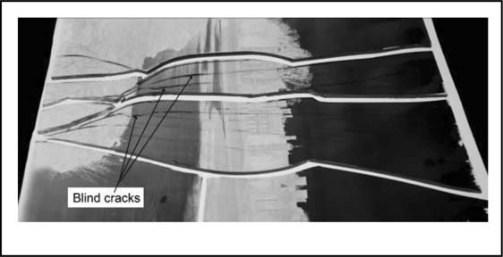
The object of this case study was an 8 × 10 inch gelatine glass plate negative, titled Charlecote from across Avon, which was taken around 1910 by Catherine Weed Barnes Ward (1851 - 1913) of Albany, New York. The plate was broken into 6 shards with numerous blind cracks (cracks that have not spread through the entire surface and have not broken the gelatin binder) in the central pieces (Figure 1). Many of the blind cracks did not run perpendicular to the glass surfaces, creating distracting dark lines when viewed with transmitted light. The plate shards had been sandwiched between two pieces of glass and bound around the perimeter with P-90 Filmoplast. Within the glass sandwich, a spacer, approximately 0.5 cm wide, had been placed between the glass and the binder side of the plate. The shards had been placed into the sandwich in contact with each other. There are two small areas of gelatin loss in the bottom left corner, another two small areas in the top right corner, and two very small areas in the sky area (the upper third of the photographic image). There is discolouration in the bottom left corner. Many areas of binder loss were also revealed with the removal of the glass sandwich housing. The final image material is in generally good condition with some mirroring visible around the perimeter of the image, in the D-max areas.
Figure 1. Shards illustrating blind cracks.
The purpose of this treatment was to repair the broken glass support and consolidate the broken gelatine binder. Before assembling any plate, the pieces should be housed in a shallow box, binder side up, on a cushion of Ethafoam and sintered Teflon©. Non-woven polyester should not be used because the fibers can catch on loose binder or splinters of glass.
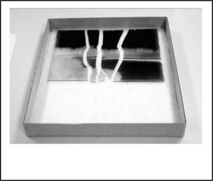
Figure 2. Object box lined with Ethafoam© and Telfon.
If there are many small pieces and blind cracks, it may be advisable to assemble the pieces in PhotoShop first, to minimize handling. To assemble the shards virtually in PhotoShop, first document the shards, all at once, with transmitted light. Open that photograph in PhotoShop, select each of the shards in turn, and make them separate layers in succession. Each of the shards can then be manipulated using the rotate and move tools.
Clean the glass plate and remove housing adhesive residue:
The P-90 residue was removed from the perimeter of the plate with ethanol/water (3:1) swabs. The glass side of the plate was cleaned with ethanol/water (3:1) swabs. The shard interfaces were cleaned with acetone, and inspected with a microscope to ensure that they were clean.
Consolidate lifting binder:
Lifting binder was laid down with 2% photographic grade gelatine, applied with a small brush, covered with a piece of silicone-release Mylar©, and pressed with gentle finger pressure. This was then left to set under light weight.
Consolidate blind cracks in the glass:
Blind cracks and breaks that had not broken the gelatine were stabilized with warmed, 20% B-72 in toluene, applied with a steel wool swab (see wicking adhesive, below), and dried under lightweight.
Assemble plate vertically:
The shards were assembled vertically with the aid of a lightline, and held in place with Vigor© sticky wax (see assembly notes below). Before each placement, the fracture line of each shard was swabbed with an acetone soaked swab and inspected to ensure that the shard-fracture interface was as clean as possible.
Wick in adhesive:
20% B-72 in toluene was wicked into the fracture interfaces using a steel wool swab as an applicator. A fibre optic light was set up to illuminate the fracture interfaces, and to permit observation of the progress of the adhesive. Once the adhesive was fully applied, the plate was left undisturbed overnight. The assembled plate was then backed with silicone-release Mylar©, a piece of stiff board and laid flat to cure for two weeks.
Clean the glass side of the plate: Once the adhesive was fully cured, the sticky wax was removed with a heated scalpel (Figure 3) and Naphtha swabs. The excess B-72 was removed with B-72 swabs.
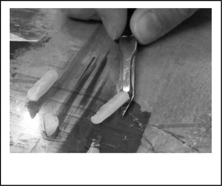
Figure 3. Removal of sticky wax with a heated scalpel.
7. Create a secondary support of clear Silicone:
The repaired plate was faced on the emulsion side with a sheet of glass of equal size and sealed around the perimeter with sticky wax (Figure 4), applied with a modified hot glue gun. A barrier of silicone release Mylar(c) was placed between the two sheets of glass to protect the emulsion.
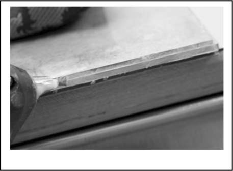
Figure 4. Application of wax seal.
This package was then placed in a Plexiglas© box that matched the outer dimensions of the glass sandwich. The box was lined with a thin, sintered Teflon© and had a removable bottom made of corrugated board. The removable bottom will facilitate removal of the plates once the silicone has set.
Clear P-4 silicone, was then mixed in a 1:10 ratio of catalyst to base, in a disposable clear plastic cup. Enough silicone was mixed to create a backing that was 0.2 - 0.25 of an inch thick (Error! Reference source not found. Figure 5). The fully mixed silicone was poured onto the center of the glass side of the plate and allowed to flow into the four corners of the mold. P-4 is a low viscosity Silicone that has a curing time of about four hours. Any air bubbles will rise to the surface and dissipate in that time.
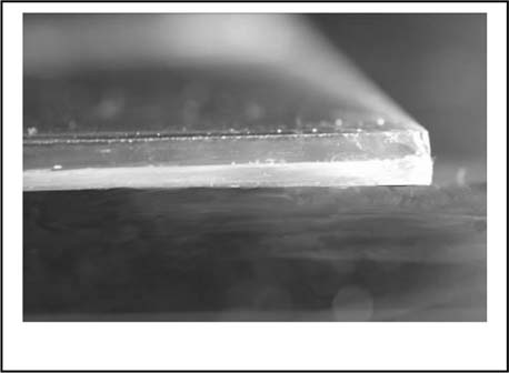
Figure 5. Silicone backed glass plate.
Once cured, the plate was removed from the Plexiglas© by gently manipulating the bottom of the box to release the silicone. The facing glass and silicone-release Mylar© were then separated by removing the wax seal with a scalpel and Naphtha swabs.
8. Create a glass sandwich:
Two sheets of framing glass, both cut 0.5 inch larger than the image plate on each side for a final size of 9 × 11 inches, were placed on either side of the silicone/glass plate. Spacers, made of four pieces of Permalife© paper, were placed around the perimeter of the emulsion side of the glass plate, and filler material of Ethafoam©, was placed around the perimeter of the silicone/glass plate. The entire package was then bound with P-90 Filmoplast (Figure 6).
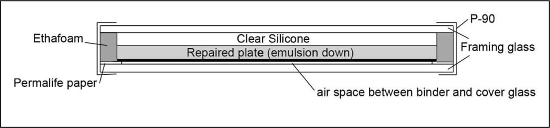
Figure 6. Repaired plate package.
Of concern with this housing is the possibility of glass deterioration. Another broken plate, brought into the conservation lab for treatment, had been housed in a glass sandwich. The glass side of the negative that was touching the housing glass showed moderate glass deterioration. There were crystals throughout the surface. The reason for this phenomenon is a combination of interacting factors: the use of inferior sandwiching glass (i.e. not borosilicate glass) and trapped moisture migrating within the sandwich. When an inferior glass, that is more prone to deterioration, is used, the likelihood of the alkali leaching out of the glass structure in humid conditions is much higher. Placing two pieces of this material into intimate contact compounds the problem.
Further, the shards had also been placed into the sandwich in contact with each other. This made it difficult to remove the shards from the housing without grinding them together. Such action could lead to further damage to the image binder. Broken glass plate transparencies should not be stored with the shards in contact with each other. They are very fragile and easily chipped. In addition, the P-90 Filmoplast tape was stuck to the edges of the glass, risking damage to the binder in that area. A barrier of thin Polyester film (0.001″) or microcrystalline wax should be placed on this edge before the P-90 is applied so that this adhesion does not occur.
The completed glass housing created for this project is discussed in detail below.
When dealing with non-planar flat glass, such as that found in most historic glass plates, the only constant force one can rely on is gravity. It is virtually impossible to assemble non-planar glass precisely on a non-vertical surface: the subtle topography of the glass surface, combined with the forces of gravity, prevents their precise alignment. Breaks in glass are brittle and not plastic; therefore, broken glass can fit together properly in only one way. To assemble glass plates precisely, vertical assembly is recommended by Stephen Koob, head of conservation at the Corning Museum of Glass in Corning, New York. With the proper precautions, this method can be highly successful for the assembly of broken glass plates of up to about 8 × 10 inches in size. For larger plates, that are thick enough to safely assemble vertically, it is advisable to set up a thick (8 ply) matboard support on the binder side of the plate. This will add stability during the assembly process. With practice, a conservator will get the “feel” for assembling the shards.
When reassembling glass plates vertically, a large shard must first be selected as the base piece. This piece must be supported so that it is at a 90° angle to a leveled horizontal surface. During the example treatment, a bubble level was used to insure that the clamp was horizontal, and mat board was used to shore up the far end of the clamp. The wooden section of the clamp rested on a thin piece of Ethafoam©, so that the bottom edge of the plate was protected. The largest piece was then placed in the clamp, binder side away from the sitter, with a piece of silicone release Mylar© between the plate and the cork of the clamp. Weights were placed on the far end of the clamp to ensure the plate was stable (Figure 7).
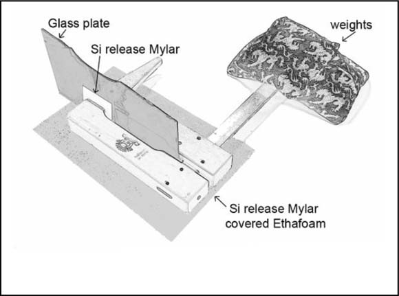
Figure 7. Clamped and weighted plate set at a 90° angle to a horizontal surface.
Vertical assembly, with the aid of a “lightline” will assure the proper placement of the glass shards. A straight line of light, created by a fibre-optic array, will also aid this process greatly. When the light is directed onto the shard interface, not at a 90° angle to the interface, any misalignment will be marked by a crooked line (Figure 8). As the pieces are brought into alignment, the lightline will become a straight line (Figure 9). A less expensive alternative to the lightline could be a flashlight fitted with a snoot that creates a straight line of light: any straight-edged beam of light will suffice.
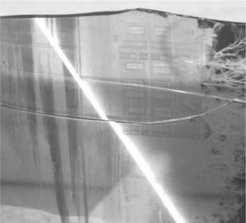
Figure 8. Misaligned shards, note the straight light line. the jagged light line.
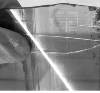
Figure 9. Aligned shards, note the straight light line.
As the pieces are assembled, sticky wax, such as that used for lost-wax casting in jewelry making, is very useful for holding the shards in place. The wax comes in sticks that can be cut into lengths as needed. Using a pin to hold the wax, warm the wax slightly over an alcohol lamp and place it on the glass side of the assembled shards (Figure 10). Enough pieces of wax should be used at sufficient intervals to support the glass as much as possible without impeding the wicking-in of the adhesive later in the treatment: one piece of wax for every four centimeters of shard interface is suggested. When the plate is completely assembled, the lightline should cast a straight line across all of the shard interfaces.
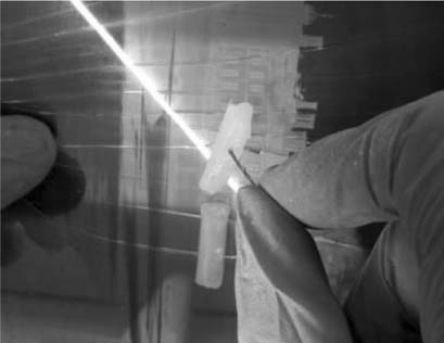
Figure 10. Tacking shard in place with sticky wax.
Assembly of the pieces should be performed in a sequence that will not call for the placement of a shard that will cause an acute angle to form (Figure 11). The sharp edges of glass fragments will typically prohibit the insertion of an acute-angled fragment into an acute-angled area. If need be, two shards can be positioned at once to avoid this situation. With the correct order of assembly, this eventuality can be prevented.
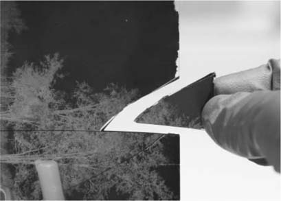
Figure 11. An example of improper assembly of an acute angled shard.
In this method of assembly, a steel wool swab (Figure 12) is very useful for the application of adhesive. The swab acts like the nib of a fountain pen, holding the adhesive and feeding it into the shard interface. Capillary action pulls the required amount of adhesive into the interface with minimal excess. An alternative to this tool could be a dosing bottle and tip. These bottles and tips cost about $17 USD for ten bottles and $12 USD for ten of the smallest size dosing tips, and are available from Cyberbond Incorporated.
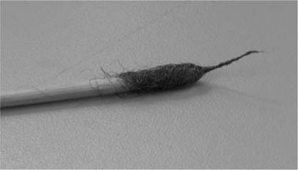
Figure 12. Steel wool swab.
Blind cracks need to be stabilized before assembly because they will be difficult to handle during assembly: the gelatine binder will shrink over time and tend to pull the glass shards apart; as a result, blind cracks may become full breaks. Warmed adhesive should be used, and ideally, the glass should be warm, so that the adhesive will flow further into the cracks. However, the warming of a gelatin plate could have adverse effects on the binder, more research needs to be conducted in this area. There may be a small air bubble trapped at the very tip of the crack, but this will tend to be minimal.
Figures 13, 14, and 15 illustrate the wicking of the adhesive into the shard interfaces. In this treatment, 20% B-72 in toluene was used. figure 13 is a close-up shot of the shard interface before wicking, lit with the light line on the edge of the plate to illuminate the interior of the plate and highlight the fractures. The wicking occurs very quickly along the interface. figure 14 illustrates the wicking-in of the B-72: the area that has received the adhesive is to the left of the swab and has become transparent because the refractive index of the B-72 matches that of the glass plate. A fibre optic light trained on the edge of the glass plate will illuminate the fracture lines, allowing for the observation of the wicking adhesive. figure 15 shows the shard interface with the adhesive fully applied.
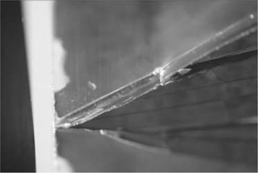
Figure 13. Aligned shards before adhesive application.
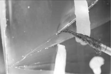
Figure 14. During adhesive application.
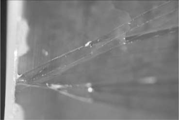
Figure 15. After adhesive application.
As a rule, a glass plate that has been broken into many pieces, or is larger than 5 × 7 inches, will require a secondary support as a part of its housing. P-4 clear silicone, has passed the PAT and is appropriate for use with photographic materials. In this case, the silicone was used as a barrier layer between the glass side of the repaired plate and the backing glass.
Figure 16 illustrates the final plate package. The clear silicone was backed with another sheet of framing glass that measures 0.5 inch larger than the perimeter of the image plate. A filler material of Ethafoam© was used to fill the gap around the perimeter. Permalife© paper, cut slightly wider than the Ethafoam© filler, was placed against the emulsion side of the image plate to create an air space between the emulsion and the cover glass. The package was then bound around the perimeter with one piece of 2-inch P-90 Filmoplast tape to create a seal.
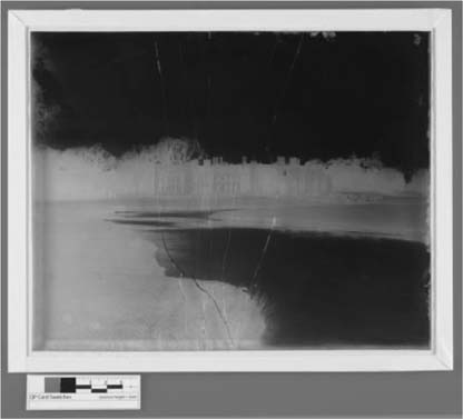
Figure 16. The final plate package.
This package creates a stable support for the entire plate that permits viewing of the entire image. For large format photographs on glass that have been broken, this treatment will make the plate accessible to researchers and protect the image from further damage.
While this research has offered many new treatment options for broken photographs on glass, it has raised new questions as well. The chemistry of glass deterioration as it relates to photographs on glass merits more extensive exploration. Moreover, the physical and chemical stability of the glass sandwich needs to be examined much more closely.
Silicone release Mylar© - Talas, http://talasonline.com
Ethafoam© - Talas, http://talasonline.com
Permalife© paper - Talas, http://talasonline.com
Paraloid B-72 - Conservation Resources International, http://conservationresources.com
Vigor sticky wax - Kingsley North Inc., http://www.kingsleynorth.com
Sintered Teflon© - Plastomer Products Coltec Industries, 23 Friends Lane, Newtown, Pa. 18940, (800) 618–4670
Clear P-4 Silicone - Silicones Incorporated, silicones-inc.com
The authors would like to thank Jiuan-Jiuan Chen for her encouragements, Amanda Gould, Aurélie Perreux, Maryann Whitman, the Andrew W. Mellon foundation, Stephen Koob, Grant Romer, Mark Osterman, Stacey VanDenburg and all of the fellows of the fourth cycle of the Advanced Residency program.
Papers presented in Topics in Photographic Preservation, Volume Twelve have not undergone a formal process of peer review.