Topics in Photographic Preservation 1993, Volume 5, Article 16 (pp. 151-152)
It has been seven years since the publication of our initial article on a homemade suction table appeared in Volume I of Topics in Photographic Preservation (Holly Maxson, 1986). This table design was the joint effort of a group of conservators in the Philadelphia/Wilmington area, and at that time, individual tables were assembled for members of the group by John Mayer.
However, because an update was promised in that first article, and there have been some minor design changes in the interim, I am taking this opportunity to be more specific about the current tables being constructed.
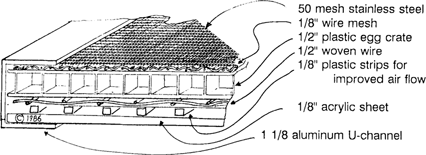
Cross Section of the Suction Table

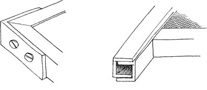
The mitred lengths of U-channel are braced at the corners with an L-shaped piece of aluminum which is 1/8″ thick. Steel screws are counter sunk on both sides of the corner brace. At one corner, the aluminum U-channel is allowed to extend 2–3″.

The first tables incorporated a side-mounted hose attachment. The plastic attachment was mounted in top of a rubber or cork gasket with several self-tapping screws. Due to the slight curvature of the plastic piece, this attachment protruded beyond the plane of the table surface. Because tension from the vacuum hose on the plastic fitting caused a slight torque to the side moulding of aluminum U-channel, we considered a modification.
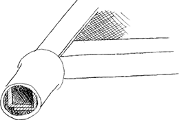
The hose attachment we are now using is a cylindrical, stainless steel sink tailpiece. The flared end of the tailpiece fits snugly over the protruding U-channel at one corner. Any small spaces are sealed with epoxy. The interior of the cylinder is 1 1/4″ while the outside diameter is closer to 1 1/2″. This fitting is in plane with the table and is in a position of greater strength.

For the past six years, I have assumed the responsibility of constructing each custom-built suction table as it is ordered. For further information, I can be contacted by phone (215) 923–4929, or by writing: Franklin Shores, 612 S. Ninth Street, Philadelphia, PA 19147.