Topics in Photographic Preservation 2009, Volume 13, Article 13 (pp. 67-82)
Presented at the 2009 PMG Winter Meeting in Tucson, Arizona
The Eastman Kodak Co. and their coupler-incorporated chromogenic print process, were nearly synonymous with the 20th century color snapshot. Introduced in 1942 and still manufactured today, samples of these prints from intervals across the manufacturing history were studied in detail in order to gain a fuller understanding of the material characteristics of this photographic process. The following aspects of the prints were examined: support, dye cloud structure, layer order, backprinting and stamps, dye and coupler stability, and fluorescence. The prints were documented overall and in cross-section under both visible and UV radiation, using an Olympus AX-70 compound microscope, and a Canon EOS 5D digital SLR. Changes in the print characteristics over time were documented and when possible, correlated to known technological developments. The documentation of these changes over time made it possible to date nearly any print to within a few years. Subsequent findings from this inquiry significantly add to the knowledge about these ubiquitous yet rarely studied photographic prints.
The era of the color snapshot began in January 1942 when Kodak introduced Kodacolor--the first consumer-oriented mass production negative/positive color print process. The process, which produced fiber base color prints from color negatives, was dramatically simpler and cheaper than previous alternatives. One of the innovations of this new process was the use of coupler-incorporated negative film and print materials. Issues with color rendition and extremely poor dye stability plagued the process in its early years, though technological innovations led to gradual improvements in print quality and stability. By 1960, color photography overtook black and white in the U.S. amateur photofinishing market.
A general introduction to the history and technology of chromogenic materials will lay the foundation for an understanding of print characteristics. Aspects of support, dye cloud structure, layer order, backprinting and stamps, dye and coupler stability, and fluorescence will be examined in detail.
NOTE: All references to chromogenic prints in this study refer to Kodak’s coupler-incorporated print materials that were sold under the Kodacolor and Ektacolor names beginning in 1942.
Chromogenic photography is based on silver halide technology, so much so that color prints are often referred to as silver halide prints in industry. The critical step in silver halide photography that we are concerned with here is the developing step:
Developer + Silver halide → Oxidized developer + Metallic Silver
In black and white photography this oxidized developer has no purpose, and is simply washed out of the print as a chemical by-product of the development process. In chromogenic processes, this oxidized developer is used for the image-wise creation of color dyes.
Perhaps the earliest suggestion for using oxidized developer to create color comes from Dr. Benno Homolka, a German chemist. Around 1906, Homolka was investigating the nature of the latent image. Specifically he wanted to determine whether the latent image acted as an oxidizing agent in relation to organic compounds other than typical photographic developers. In order to make this task easier he sought an organic compound whose oxidized form was both colored and insoluble. This way, if the latent image acted as an oxidizing agent, the oxidized organic compound would stay in the emulsion and be visible. He chose two close chemical relatives of indigo dyes, indoxyl and thio-indoxyl. Upon oxidation these convert to insoluble green and red compounds, respectively. While Homolka did note the beautiful photographic effects that could be obtained with these new “developers”, he did not suggest that these reactions might be useful in the pursuit of a color photographic process (Homolka 1907).
A few years later, another German chemist, Rudolf Fischer, would be the first to recognize the potential of oxidized developers in producing a photographic color image. In a patent filed in 1912, Fischer coined the terms “color development” and “color formers” (dye couplers), and described the process of chromogenic negative/positive photography in some detail (Fischer 1913). A year later, he listed the color developers and dye couplers that can be used in combination to produce various colors in the “making of colored photographs,” many of which are still in use today (Fischer 1914). With Fischer’s work we can now complete the chromogenic chemical reaction:
Color developer + Silver halide → Oxidized color developer + Metallic Silver
Oxidized color developer + Dye coupler → Color dye
Despite his visionary description of chromogenic photography, Fischer was not able to create a successful color process. He could not prevent the sensitizing dyes and dye couplers from wandering between the various emulsion layers and causing havoc in the final image. Research at Agfa and Kodak in the 1920s and 1930s would finally solve these problems and pave the way for the introduction of Agfacolor Neu in 1936 (a chromogenic color transparency process) and finally for Kodacolor in 1942.
One of the last steps in solving the practical problems of the chromogenic process was the anchoring of the color couplers to keep them from wandering into other layers or diffusing within their own layer. Agfa was the first to solve this problem. In the early 1930s Wilmanns and Schneider, working at Agfa Filmfabrik, discovered that the diffusion properties of dyes within a gelatin layer were dependent on the shape of the dye molecule, and that long molecules did not easily diffuse. This soon led to the development and patenting of dye couplers with long carbon chains attached to keep them in place in the gelatin binder. This was the key discovery that made it possible for Agfa to produce Agfacolor Neu.
Kodak was working on the same problem, but found a different solution around 1939. They used shorter carbon tails on the dye couplers, making them water insoluble and oil-soluble. They then dissolved these dye couplers in a resinous binder, which was then dispersed as tiny droplets in the gelatin emulsion. This discovery led directly to the introduction of the Kodacolor process in January 1942 (Coote 1993).
KODACOLOR/EKTACOLOR TIMELINE
1942 Kodacolor introduced (very poor dye stability, severe coupler staining)
1949 Orange coupler mask replaces silver image mask in Kodacolor negatives to improve color rendition
1954 Magenta dye stability improved, coupler staining dramatically reduced, dye layer order reversed
1959 Cyan dye stability improved, coupler staining further reduced, OBAs added during processing, backprinting introduced with Kodak Penny Seal (EKC logo)
1968 Resin-coated (RC) supports and textured surfaces introduced
1974 Optical Brightening Agents (OBAs) added to paper base during manufacture
1988 OBAs added to polyethylene layers
SUPPORTS
Kodak has used 4 different supports since 1942 for their chromogenic prints: fiber base, resin-coated (RC), polyester, and laminate.
Fiber base support was used for Kodak chromogenic prints from their introduction in 1942 until it was replaced by RC support in 1968. Fiber base prints were being produced as late as 1971, as evidenced by a sample book from that year. Fiber base support consists of paper, or “raw base” as it was called at Kodak, and a baryta coating. Here is a list of additives to Kodak’s raw base from 1945:
Muriatic acid (pH adjustment)
Melamine-formaldehyde (Wet strength agent)
Aluminum chloride
Stearic Acid/NaOH (produces sodium stearate, and mixes with AlCl3 to make AluminumStearate which acts as an internal size providing increased water resistance)
Gelatin tub size (external gelatin size, could provide wet strength if hardened, generally acts as asurface sizing agent, holds down the paper fibers, etc.)
Blue dye used in most papers
Magenta dye used in about 5% of papers
Corn starch (dry strength)
Beater gelatin (dry strength)
RC supports were made by sandwiching the raw base between layers of polyethylene (PE). Theemulsion-side PE layer was pigmented with titanium dioxide (TiO2). TiO2 imparts opacity and whiteness to the pigmented PE layer, replacing the visual function of the baryta layer in fiberbase prints. Both rutile and anatase forms of TiO2 have been used, though surface treatmentshave been changed over time to reduce the light induced oxidation of the RC support which iscatalyzed by TiO2. TiO2 surface treatments also prevent clumping and help dispersion of theparticles. TiO2 was added to the raw base of RC supports around 1984. Although the detailedcomposition of print supports are not known for every time period, after 1988 the layers and additives of Kodak RC color prints were as follows, though some additives may not be listed,and the composition may have changed at some point:
Emulsion layers (CMY)
Pigmented PE layer: TiO2, Zinc Oxide, OBA, Magenta dye
Raw Base: paper fiber, antioxidants, TiO2, OBA
Backprinting
Clear PE layer
Anti-static layer (colloidal silica)
Polyester supports were first used for Kodak chromogenic prints in the 1970s with ID print materials, and their use was later expanded into professional papers. Manufactured in transparent, pigmented translucent, and pigmented opaque base, polyester supports have had aniche market since the 1980s. The opaque base was discontinued in 2004, while transparent and translucent materials are available to this day (Eastman 2004).
Laminate supports have been used for two products: Duralife, a short-lived consumer product introduced in 1999, and Metallic Endura, a professional paper with a metallic appearance. Thesesupports have a complex laminate structure, and resist tearing and curling.
SURFACES
Fiber base print surfaces: F (glossy), air-dried or ferrotyped Fiber base prints (1942-1968) were only manufactured with an F surface (glossy), which could be ferrotyped or air-dried, giving two possible surfaces for fiber base color prints. Photofinishing prints were nearly always ferrotyped.
RC print surfaces: F (glossy), N (matte), Y (silk), E (lustre)
Kodak converted from fiber base to RC for Kodak chromogenic color prints in 1968, making available a wider range of manufactured surfaces for color prints. RC print surfaces were made in an entirely new way. After the PE layers were extruded onto the paper base, the support was passed through a nip, and cooled against a textured steel roller, known as the chill roll. The only exception to this was the silk surface, which was originally made by embossing the cooled RC support, and later was made with the chill roll.
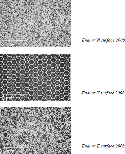
Figure 1. Textured Rc print surfaces
Matte and Silk surfaces were introduced in 1968 (Eastman 1974). Silk was the photofinishing surface of choice in the early 70s, though it was abruptly displaced by E surface in 1976. By 1977, Y surface accounted for only 1% of photofinishing prints (Wolfman 1975-77).
Polyester print surfaces: Ultra-high gloss
Kodak’s polyester-base prints have an ultra-high gloss similar to the surface of polyester or acetate-base Cibachrome prints.
Laminate print surfaces: Glossy
Laminate prints (Duralife and Metallic Endura) have a high gloss surface, similar to an F surface RC print.
DYE LAYERS
The conventional emulsion dye layer order of chromogenic photographic materials is (from top to bottom) yellow, magenta, cyan (YMC). Light passes through the blue-sensitive (yellow) layer first, then the green-sensitive (magenta) layer, and finally the red-sensitive (cyan) layer. This allows the use of a yellow filter layer below the blue-sensitive layer, which prevents exposure of the two lower layers to blue light. When the Kodacolor negative-positive system was introduced in 1942, both the film and paper were arranged in this conventional layer order. In 1954, the paper dye layer order for negative working prints was reversed to (top to bottom) cyan, magenta, yellow (CMY). The cyan layer was moved to the top of the emulsion, away from the relatively rough surface of the baryta, in part to reduce perceived mottling because the human eye can distinguish detail more readily in cyan than in yellow. This layer order remains in use today for all negative-working print materials, however positive-working print materials have always retained the traditional YMC layer order.
The use of a yellow filter layer is not possible with the CMY layer order because the blue-sensitive (yellow) dye layer is on the bottom. Instead, blue light must pass through the red-and green-sensitive layers to reach the bottom blue-sensitive layer. The obvious difficulty with this setup is that silver halides have inherent blue sensitivity, regardless of how they have been sensitized to red or green light. Therefore, to make this work the bottom blue-sensitive layer must have greater light sensitivity. This allows relatively small amounts of blue light to pass through the red-and green-sensitive layers and sufficiently expose the blue-sensitive layer.
This new dye layer order with yellow on the bottom has remained unchanged for Kodak chromogenic negative-working print materials. Film has maintained the conventional YMC layer order (photographic still film only, motion picture film varies). Kodak reversal print materials such as Ektachrome paper also use the YMC layer order, as well as other reversal print materials such as Cibachrome. Layer order can be determined non-destructively by using a compound microscope with reflected cross-polarized light at 500x viewing magnification. The limited depth of field at this magnification makes it possible to focus on only one dye layer at a time, thus enabling layer order to be determined by observing the order that these layers come into focus.
DYE CLOUDS
The dye deposits formed in the coupling reaction between oxidized developer and dye coupler are known as dye clouds. These dye clouds form in the immediate vicinity of developed silver. After development of the silver and color dyes, the silver is removed through bleaching and fixing, leaving only the dye clouds to form the image. The size of dye clouds is a function of the diffusion rate of oxidized developer (how quickly the developer molecules travel through the gelatin after reducing the silver halide to metallic silver), the coupling rate (how quickly the oxidized developer reacts with the dye coupler), and the reactions of the oxidized developer with substances other than the coupler (Krause 1989).
In Kodak chromogenic papers dye clouds range in diameter from 1.25 to 4 microns. Yellow dye clouds tend to be larger than their cyan and magenta counterparts. One of the primary means of achieving a high-speed emulsion (which is necessary for the blue-sensitive dye layer) is the use of large silver halide grains, which in turn leads to large dye clouds.
Dye clouds in Kodak negative working prints can be divided into three distinct eras when examined with reflected cross-polarized light at very high magnifications (a 500x viewing magnification on a compound microscope was used in this study). Changes in emulsion manufacture and processing resulted in the edges of dye clouds becoming less diffuse over time, and this can be used in the dating of prints by classification into one of the three groups. The first period is from 1942 through the 1960s, and is identifiable by diffuse dye clouds. Starting in the early 1970s, dye clouds become slightly more defined, having a relatively circular shape with a moderately defined edge. This lasts until the early 1980s when dye clouds become very well defined with hard edges. This period continues to the current day. Since dye clouds in negative and positive working prints evolved at different rates it is imperative to determine layer order, and thus material, before using dye clouds to date prints.
IMAGE DETERIORATION
Image deterioration of chromogenic prints occurs in three primary ways: thermal fading, light fading, and coupler staining. Thermal fading, or dark fading, refers to color image dye loss that occurs by the action of temperature and humidity. Until the 1980s, cyan dye was generally the most susceptible to thermal fading. Therefore, the effect of thermal fading alone on prints of this era has or will be a reddish image tone resulting from a loss of cyan dye. Light fading reveals a different dye weakness. The magenta dye is typically the weakest when exposed to light, and prints left on display will typically become cyan or green in color. Coupler staining is the yellow cast caused by the magenta coupler that remains in the print in inverse proportion to the amount of magenta dye. Wherever magenta dye is not formed, there is magenta coupler that remains in the print after processing. This coupler can yellow in one of two ways: thermal yellowing or coupler print-out. Thermal yellowing, like thermal fading, occurs without light, while coupler print-out is the yellowing that occurs in response to light exposure. Coupler staining has been systematically improved since 1942 (LaBarca and O’Dell 2002, Reilly 1998).
All of these forms of image deterioration can be found on any print in varying degrees. Of course, they are more obvious in older prints that are both less stable and have had more time to deteriorate. While it can be difficult to interpret every nuance of image deterioration in a given print, there are general trends that become quickly apparent when large numbers of prints are examined. These are described here by the five major eras of image deterioration:
1942-54
Early Kodak chromogenic prints, from their introduction in 1942 until 1954, had both very poordye stability and severe coupler staining. These prints are easily recognizable by their dramaticyellow stain in non-image areas, and the nearly complete absence of color in the images, which have faded to brown with only hints of the original dyes.
1954-59
In 1954 Kodak made significant improvements in magenta dye stability and drastically reduced coupler staining. Prints from the period of 1954 to 1959 are identifiable by their overall magentaimage color and only slight coupler staining compared to pre-1954 prints.
1959-1968
In 1959 Kodak introduced prints with even further reduced coupler staining and drastically improved dye stability. These prints do not exhibit overtly characteristic image deterioration.They generally have pleasing overall image colors with only mild dye fade, unless they were lefton display over a long period.
1968-1980
With the introduction of RC prints in 1968 a new deterioration problem was created:embrittlement and cracking of the emulsion side PE layer. This problem is unique to RC printsand was corrected by 1980. It was not examined in any detail in this study.
1980-2008
Kodak continued to make improvements in coupler staining and dye stability, particularlybalancing relative thermal and light fading rates to improve long-term appearance. Newpyrazolotriazole magenta couplers virtually eliminated thermal yellowing and coupler print-outby the late 1980s (LaBarca and O’Dell 2002). A new cyan dye in the early 1980s made yellowthe new weak link in thermal fading.
OPTICAL BRIGHTENING AGENTS
Optical brightening agents (OBAs) can be found in chromogenic prints by 1959. OBAs wereadded to prints from 1959 until 1974 by inclusion in the processing chemistry. Since they werenot added during manufacture, some prints from this period do not contain OBAs. Kodakincluded OBAs in the raw base during manufacture starting in 1974. The final change occurredin 1988 when Kodak added OBAs to the polyethylene layers of RC prints (Keirstead 2008).
An effective method for determining the presence or absence of OBAs is to view the print inquestion under dim tungsten lighting next to a print without OBAs (such as an early 1950sKodacolor print). Then turn on a UV-A lamp near the prints and look for any change. Prints with OBAs fluoresce under UV, appearing brighter and with a blue cast. It may be helpful to switch the UV lamp off and on again several times to look for any change. The use of a UV lamp byitself can be misleading, as the blue visible light emitted by the lamp can easily be confused with fluorescence when viewing the white surface of the back of the print.
Photofinishers typically process prints on a roll, a system that creates two different types of prints edges, one exposed to processing solutions and one formed by cutting the individual prints after processing. This difference is often visibly noticeable in RC prints by the staining of the paper fibers on the chemistry exposed (manufacturer cut) edges. An effect that can be used to date prints to before or after 1974 is the presence of OBAs in the paper fibers on the non-chemistry exposed (processor cut) edges. This indicates that OBAs were added during manufacturing, a practice not begun by Kodak until 1974. This can be determined non-destructively by examining the edges of a print under UV radiation and with high magnification (a viewing magnification of 200x on a compound microscope was used in this study).
UV ABSORBERS
UV absorbers are used to improve the light stability of color dyes. They have been used in Kodak color prints since 1950, when they were introduced in Kodacolor Type II paper (Hanley 1974). When examined under UV lamps, prints with UV absorbers appear darker than when viewed under visible light. The effect of UV absorbers on print appearance is different depending on the OBA application method (manufacturing or processing), as well as on the relative amounts of OBAs and UV absorbers.
MANUFACTURER BACKPRINTING
Backprinting was first used on Kodak color papers in October 1958 with the introduction of the Kodak penny seal, a circular emblem containing the letters “EKC.” Initially, backprinting was very faint to imitate a watermark, and was referred to as such, despite being printed. From the beginning there was controversy over the presence of the backprint and the density of the printing (Beach 1977). Photofinishers often appreciated the printing as proof of their use of quality photographic materials. Professionals often disliked it, as they preferred the photograph to be their own work, and not labeled by a manufacturer’s name. After the introduction of backprinting on Kodak color paper in 1958, unprinted paper was intermittently produced.
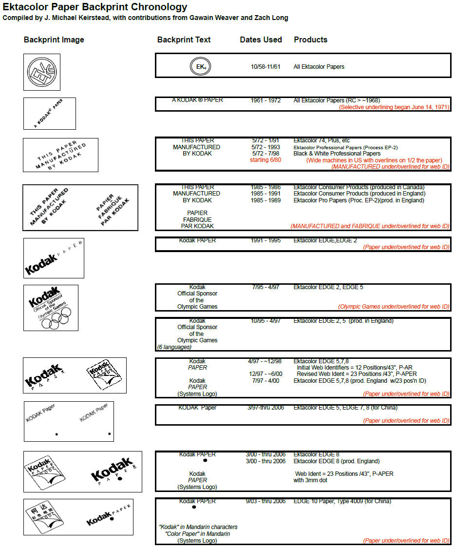
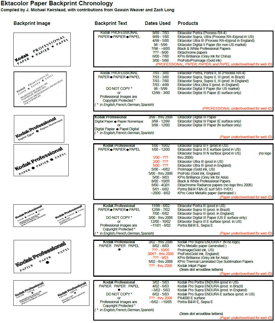
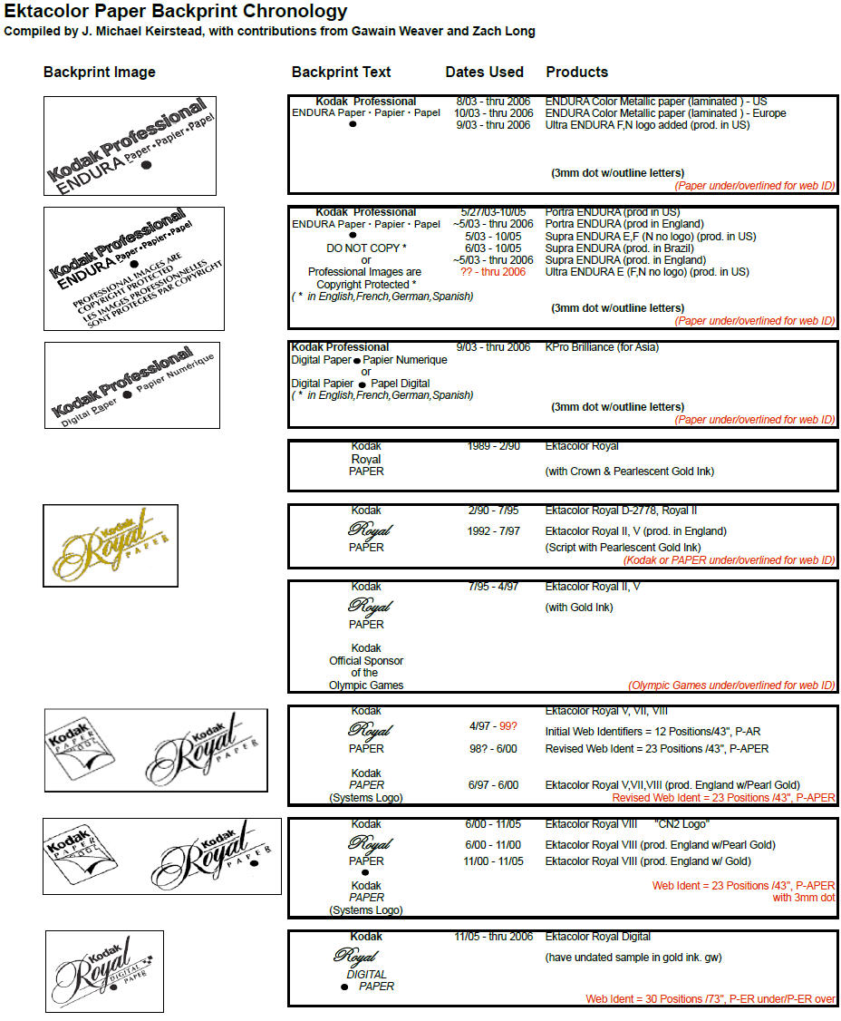
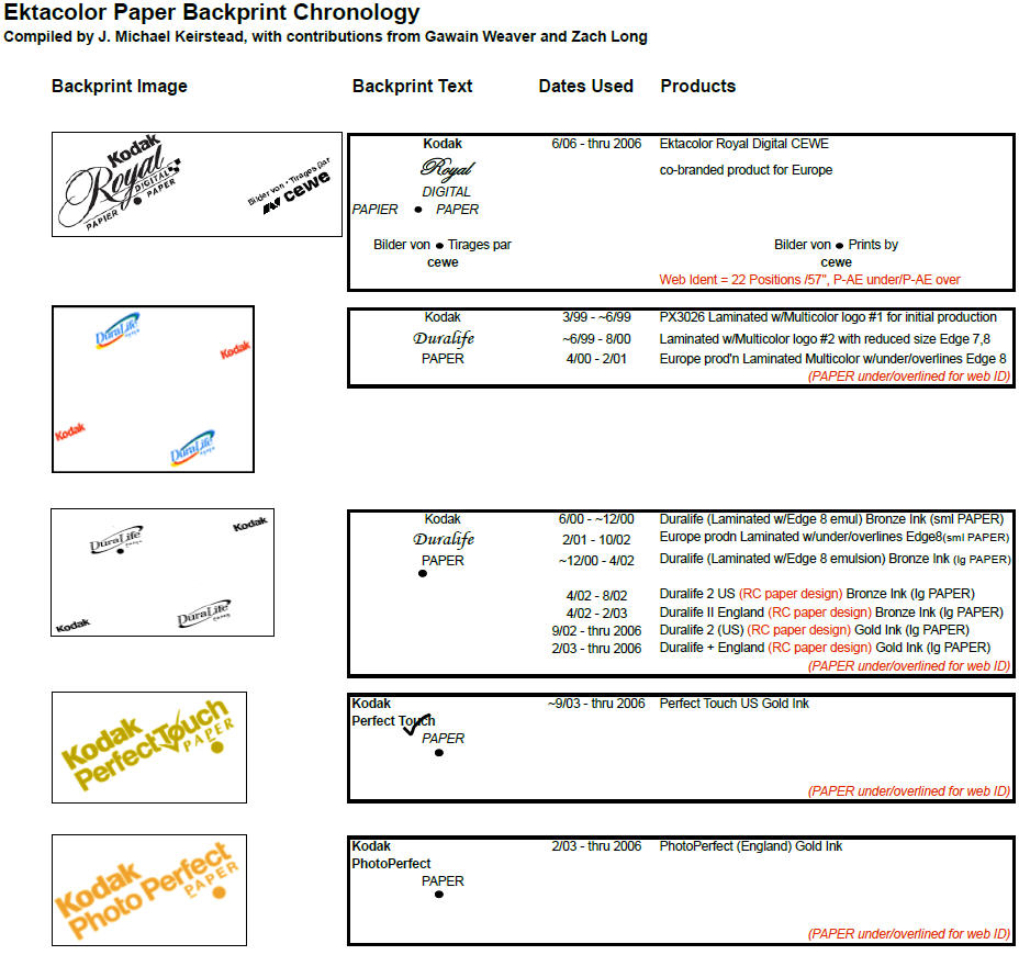
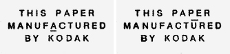
In November 1961 a new backprint symbol was introduced, which read “A Kodak ®Paper.” In 1968, this backprint made the transition onto RC paper with the introduction of Ektacolor 20 RC. Then on June 14, 1971, selective underlining of the letters in the backprint “A Kodak ®Paper” was introduced in order to identify lateral locations on the paper roll. This was useful in product control and defect tracking. In May 1972 the backprint was changed again, this time to “This Paper Manufactured by Kodak,” which lasted until around 1989. Selective overlining was introduced in addition to selective underlining in 1980, in order to accommodate new wider paper rolls (see Figure 2). In 1989 Kodak changed their model of a standard backprint for all materials to one of unique a backprint for each individual product line. This resulted in a multitude of new backprints that were often short-lived (Ward 1973, Keirstead 2008). A detailed chronology of Ektacolor backprints including images when available can be found in the chart “Ektacolor Paper Backprint Chronology” included at the end of this paper.
Figure 2. Examples of underlining and overlining on manufacturer backprints
PHOTOFINISHER BACKPRINTING AND STAMPS
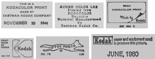
Backprinting and stamps are often added by the photofinisher, and can appear as logos, text, or both. Stamps were used by Kodak beginning in 1942 and indicated the date and identified the prints as being from Kodak. Kodak used different stamps over the years, though they are seen less frequently on prints after the 1960s. Processing by non-Kodak labs began after 1954. Stamps from these photofinishers are less common, but still readily found. Back stamps on mounted prints can often be seen using strong transmitted light. Limited experiments with documenting stamps on mounted prints with transmitted IR photography have had some success as well.
The ability to print unique lines of text, including date and print exposure information was first available in the late 1970s with the introduction of the Noritsu minilab. At first only single lines of text were possible, but beginning in the late 1980s, two lines of text became possible, and could be used for the name of the photofinisher or other information. A dot matrix printer has been used from the beginning by Noritsu, and by other manufacturers as well. While Noritsu had a large share of the minilab market, there were other manufacturers, who used their own backprinting systems. Detailed information about photofinisher backprints has not been collected.
Figure 3. Examples of photofinisher stamps on prints from 1944 to 1980
Each of the print characteristics discussed here enhances understanding of the chromogenic color print process, particularly Kodacolor/Ektacolor prints. When examining a print, these characteristics can be used to place it within the technological continuum of the chromogenic process and date it within a few years.
Succeeding work in chromogenic print characterization should study other manufacturers such as Agfa, Fuji, and Konica. Additionally, Kodak’s non-coupler-incorporated chromogenic print materials, i.e. Kodachrome type emulsion should be studied. Finally, further investigation of the print chemistry of each era needs to be understood. The use of stabilizers are of particular interest, as conservators have often wondered about the effects of water damage and aqueous conservation treatments on prints that were stabilized during processing. An understanding of all of the aspects of chromogenic print materials is of increasing importance. These materials have seen significant use by fine art photographers since the 1970s and have now been fully integrated into digital printing via digital exposure units such as the Durst Lamba. A high percentage of large contemporary prints are being produced in this way. Chromogenic prints now have significant presence in the fine arts, and still maintain a major presence in photofinishing. Our ability to safely treat and preserve these prints will be greatly enhanced by further study of the relationship between their observed characteristics, manufacture, and processing.
Thanks to James Reilly, Director, Image Permanence Institute for allowing us to pursue our curiosity about the details of chromogenic prints. This research would not have been possible without the help of several retired Kodak employees who gave generously of their time and expertise, in particular Kit Funderburk, J. Michael Keirstead, Ron Mowrey, and Paul Schwartz.
Beach, D.S. 1977. Memo on Backprinting. Kodak Historical Collection #003, Rush Rhees Library, University of Rochester.
Coote, J. 1993. The illustrated history of colour photography. Surrey: Fountain Press.
Eastman Kodak Co. 1974. Negative/Positive Color Papers. Kodak Historical Collection #003, Rush Rhees Library, University of Rochester.
Eastman Kodak Co. 2004. Kodak Professional Duraflex Plus Digital Display Material: KODAK Publication No. E-4014 . Rochester, NY.
Fischer, R. 1913. Process of making photographs in natural colors. U.S. Patent 1,055,155.
Fischer, R. 1914. Process of making colored photographs. U.S. Patent 1,102,028.
Hanley, T.G. 1974. Negative-Positive Print Paper Innovations, 18 June. Kodak Historical Collection #003, Rush Rhees Library, University of Rochester.
Heidke, R. L.H. Feldman, and C.C. Bard. 1985. Evolution of Kodak photographic color negative print papers. Journal of Imaging Technology 11(3):93-97.
Homolka, B. 1907. “Experiments on the nature of the latent image and of the negative image” British Journal of Photography. (February):136-138.
Keirstead, J.M. 2008. Interview by Gawain Weaver, 2 September. Rochester, NY.
Krause, P. 1989. Color photography. Imaging processes and materials, ed. J. Sturge, et al. 8th ed. New York: Van Nostrand Reinhold. 110-134.
LaBarca, J. and S.F. O’Dell. 2002 The importance of the balance of light and thermal image stability. IS&T’s 12th International Symposium on Photofinishing Technology. Orlando, FL.
Reilly, J. M. 1998. Storage guide for color photographic materials. Rochester, New York: Image Permanence Institute.
Ward, R.M. 1973. Memo re Kodak Backprinting, 18 May. Kodak Historical Collection #003, Rush Rhees Library, University of Rochester.
Wolfman, A. 1974-77. Wolfman Report on the Photographic Industry in the United States. Modern Photography Magazine, NY.
GAWAIN WEAVER Photograph conservator in private practice, San Rafael, CA
ZACH LONG Research assistant, Image Permanence Institute, Rochester, NY
Papers presented in Topics in Photographic Preservation, Volume Thirteen have not undergone a formal process of peer review.