Topics in Photographic Preservation 2011, Volume 14, Article 42 (pp. 282-287)
Presented at the 2011 PMG Winter Meeting in Ottawa, Canada
The preservation system is composed of a primary housing to enclose bare plate daguerreotypes and a secondary housing to contain and protect the primary housing. The housing system takes into account the requirements for preservation, research, and exhibition and offers a simple, elegant, and economical solution to protect bare plate daguerreotypes.
The primary housing protects the bare plate from mechanical damage but also allows complete view of the entire plate (both recto and verso) for research and monitoring purposes. It is designed to be dissembled easily and safely if the need arises.
The secondary housing is versatile and serves three fundamental functions: storage, exhibition, and travel. The materials and design of the secondary housing limit chemical interactions between the daguerreotype plate and the outside environment. A key component is a sacrificial corrosion inhibitor that can be easily accessed, monitored and replaced. This construction is intended to accompany the primary housing described here. However, it can also be applied to daguerreotypes in passé partout or daguerreotypes with missing cases or frames.
The construction of the overall system is flexible and should be considered on a case-by case basis to meet the specific design requirements of each plate and collection. The materials used here can be changed as long as they meet an equivalent standard for permanence.

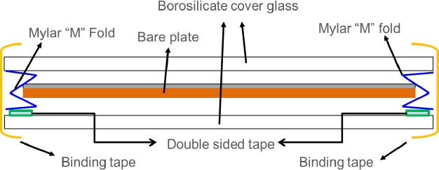
Figure 1: Design A, plate package, cross section view
The plate is suspended between two pieces of borosilicate glass. The edges of the plate are supported by Mylar “M” folds (see Figures 1 and 2). The “M” folds can be compressed to reduce the air space in the package as long as the plate is not stressed and the glass does not come into contact with the plate on either recto or verso surfaces. The “M” folds can be made in advance and applied to daguerreotypes of any sizes. The binding tape covers only the edges of the glass, allowing a complete view of the plate. “M” folds can be mitered at corners for better aesthetics or simply cut in strips for easier application.
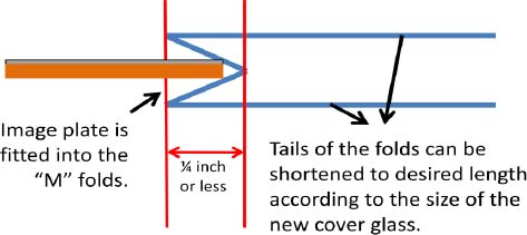
Figure 2: Mylar “M” fold, cross section view
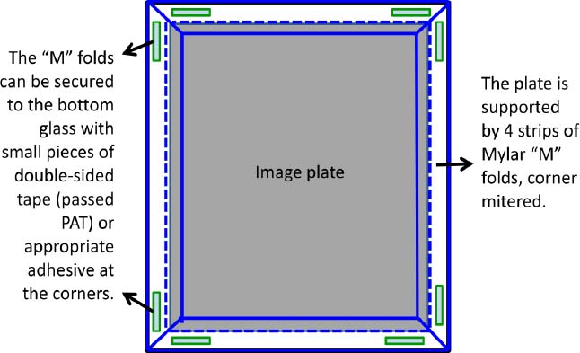
Figure 3: Design A, image plate fitted with Mylar “M” folds, top view before adding top cover glass and binding tape. “M” folds with corners mitered (option 1).
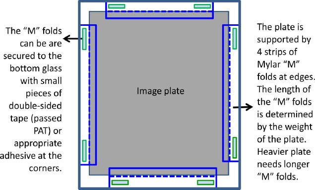
Figure 4: Design A, image plate fitted with Mylar “M” folds, top view before adding top cover glass and binding tape. “M” folds used as edge supporting strips (option 2).

Figure 5: Design B, plate package, cross section view
The plate is suspended between two pieces of borosilicate glass with the plate supported by a single piece of Mylar with folded tabs at the four edges.
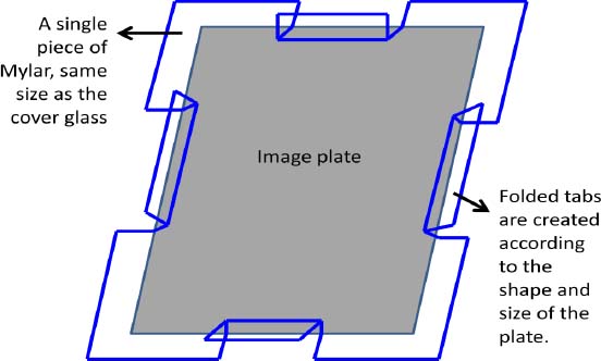
Figure 6: Design B, image plate supported by Mylar with folded tabs, top view before adding top and bottom cover glass and binding tape.
The secondary housing includes a corrosion inhibiting retainer and a custom-made container.
The corrosion inhibiting retainer is designed to make a snug fit around the edges of the primary housing. It incorporates a channel to accommodate a material such as Corrosion Intercept®. The function of Corrosion Intercept® is to chemically deplete corrosive gasses. A sacrificial material, Corrosion Intercept® will turn black when it is no longer effective and must be replaced.
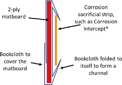
Figure 7: Corrosion inhibiting retainer, cross section view
The custom-made container is designed to fit and secure the plate package once it is wrapped inside the corrosion inhibiting retainer (See Figures 8-10). The container can be a storage box, an exhibition tray or a transportation container. Regardless of the secondary container, the corrosion inhibiting retainer must be present (see Figures 13-15). A window mat can be added to mask the binding tape and the Mylar “M” folds or Mylar edge strips for exhibition purposes (see Figures 13, 16, and 17).
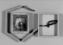
Figure 8: Components of corrosion inhibiting retainer
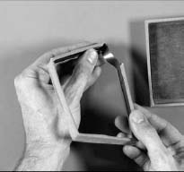
Figure 9: Fitting the strip to the channel

Figure 10: Retainer fitted around the plate package inside a tray

Figure 11: Image plate/corrosion intercept retainer in clamshell box storage/traveling container
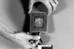
Figure 12: The corrosion intercept retainer can be accessed easily.
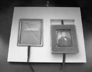
Figure 13: Image plate/corrosion intercept retainer in storage container with multiple trays
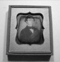
Figure 14: Image plate/corrosion intercept retainer in exhibition container
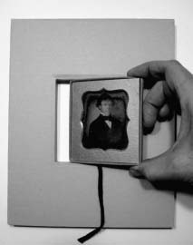
Figure 15: Fitting the image plate/corrosion intercept retainer to the sink mat
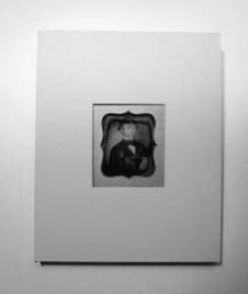
Figure 16: Overmatted
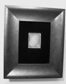
Figure 17: Plate package in exhibition frame with velvet window mat
JIUAN-JIUAN CHEN
Paul Messier, LLC
MARK BEEMAN
Independent Collections Care Specialist
Papers presented in Topics in Photographic Preservation, Volume Fourteen have not undergone a formal process of peer review.